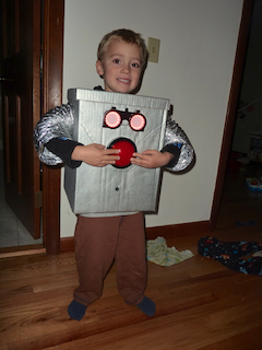
My son wearing the costume and giving a goofy smile. Scroll down to the bottom to see more pictures and a video.
Preface
I still get a bit more excited about Halloween than I’d like to admit. However, it’s a good creative outlet for me and my son certainly enjoys the fruits of my labor almost as much as I enjoy the labor. So, everyone wins, right? Last year my son had the brilliant idea of being a CFL bulb, which pretty much involved sticking a white LED strip inside of a white pool noodle and figuring out how to attach it all to a toddler along with a 12V battery. This year, though, he wanted to be a robot, which leaves a lot more room for cool lights and doodads. So, here is the HalloweenBot v2013.10.31.
Parts
- Cardboard
- Silver spray paint
- Wire
- Dryer Vent for arms
- Split wire loom (for keeping the wires neat inside)
- Electrical Tape and Duct tape
- A bit of weather stripping, for the neck hole
- 3mm nylon screws and spacers, to mount the PCB
- Clear Crayon Box ($2 when I bought mine)
- Flip-up welding goggles
- Piezo Buzzer
- 2x Neopixel Rings
- 100mm Red Arcade Button
- Half-size Perma-Proto Board
- Diffused 5mm Slow Fade Flashing RGB LED (just to make the PCB more flashy)
- ~220 Ohm current limiting resistor for the flashing rgb
- 4 x AA Battery Holder with On/Off Switch, use with NiMH only!
- 3.3V Trinket
Lots of parts, but you can certainly do without many of them, or add more, as you wish.
Schematic
I drew up the basic schematic in fritzing, but there are a few differences between this and reality:
- The RED LED on the board is actually the slow fade rgb led. This is just used to light up the board, nothing more.
- The switch isn’t the correct one - there is no normally closed pin on the 100mm switch, but the rest is fine. Note that it won’t be mounted on the board - you’ll need to run some wires to it.

Construction
This should be personalized by you (and/or your kid), but here are some guidelines.
Goggles
-
The hard plastic portion of the welding goggles comes off and can be mounted through your cardboard. Just cut out a hole that matches the profile of the plastic part.
-
Disassemble the lenses by unscrewing the black rings. Remove the dark green welding glass.

-
Grind off the little nubs in the black rings. You can’t get the neopixel ring in there if these are still on. I ground it off all of them to avoid any weird shadows. I just used a grinding wheel on my dremel to do this. I then cut a thin slot on top so I could screw the black rings back in using a fingernail.
-
Using the lenses as a template, cut out some paper for a diffuser. Put the clear lens, the paper, and then the black rings back into the inner part (the part that doens’t flip up of the goggles). After you have your neopixel ring wired up, you can fit it inside the black ring and secure it with some hot glue.
PCB

-
I used some 3mm nylon screws, spacers, and nut to mount the PCB to the lid of the crayon box because the lid is flat and the bottom has ridges.
-
I then mounted the crayon box to the outside of the robot with some sticky velcro. This was mostly because there was no room in side, but it also adds to the robot effect, especially with the color changing LED in there. The crayon box diffuses the LED light pretty well. You could paint the inside to diffuse it better, or leave it clear to show off your soldering skills (or lack of)!
-
Try not to solder on the trinket until you get the program finished. The trinkets seem a bit fragile, at least compared to an arduino. I managed to brick one of them, unfortunately.
-
When you do solder on the trinket, try to position it so it can be re-programmed via usb. I put mine off to one side. I have to unscrew a nylon nut to get the usb cable in there, but at least it can be done.
The big button
There’s not much to this, really. The LED has a resistor built-in, although it’s meant for 12V, so it’s a bit dim at 5V. If you use the internal pullup resistor in the trinket via pinMode(BUTTON_PIN, input_pullup), you can connect the LED ground to one side of the button. I initially designed the circuit with an external pulldown resistor, but I realized using the internal pullup resistor would save me routing a wire inside.
I used the button as the “nose” of the robot, because it looks pretty cute that way.
The piezo
Stick it somewhere with some hot glue and let ‘er rip. To be honest, I was a bit disappointed with the volume level at 3.3V. It’s not very loud. So, test it out and see if it’s good enough for you. If not, you now have a free pin! Instead of buzzing when the button is pressed, dispense some candy corns! Ooh, that would be awesome…
The batteries
Not much to say here except to make sure that you only use NiMH batteries. The Neopixels wouldn’t survive 4XAA alkaline batteries. You could also use a LiPo battery to reduce weight. I used 4 2200mAh Eneloops and let the robot run for 5 hours and they were still at 4.8V. So, that’s really a bit overkill.
The body
This is where you will need to really use your judgement. I basically made a box without a bottom, a little bit larger than my kid, reinforced the heck out of it, and cut holes for the arms and head. I then made the back open up to try to make it easier to get in and out of it. However, getting his arms in is still quite difficult. I’m not sure yet how to improve on this.
The Code
I think it’s fairly readable, but the basic idea is this:
- On startup, it will “randomly” select an effect from one of 4 effects
- It will repeat that effect with some “random” colors for a “random” number of times.
- If you push the button, the robot gets angry and the eyes turn red and the buzzer buzzes.
- When you release the button, it resumes with the “random” stuff.
I put random in quotes because it’s really not random. It will run the same sequence every time. Unfortunately, I ran out of room for the program, so some things didn’t make the cut. Notably, there is no seeding of the randomization.
More Pictures


